
Popular connectors for computers
Pin out tables, some photos and parts of data come from Wikipedia.
Computers have various of connectors for their diverse use case. Overtime, old standard become obselete and new connector emerges. Some of them established their ground and dominates in their domains. It’s interesting to note their capability and how they got where they are. I am going to list some of them in this post and summarize key features. If you know a little bit about past standards, you might be amazed how technology eveolves step by step. Had if you know nothing about past standards, these connectors and standards would become old in the next decade or further in the future.
USB
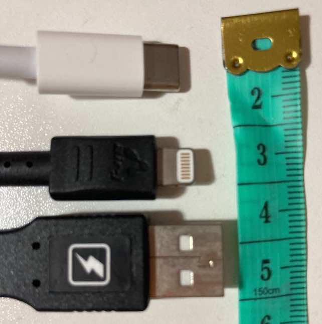
Starting from a golden standard of physical peripheral, this connector is Universal Serial Bus (USB). USB is everywhere. You can find them in laptops, cameras, drones, headsets, gaming consoles, and even industry machines. For example, latest Macbook Pro (2020) has 4 USB-C while their old predecessors have Thunderbolt connectors. Nowadays, most Android phones come with a USB-C connector.
USB has become complicated and confusing industry standard. The confusing part comes with multiple physical connector types and its different versions. Motherboards usually have different types of USB 3.x receptacles or jump wires. Despite its historical burden, the latest version, USB-C aims to move forward with all advantages and drawbacks from its past versions and receptacles. In the past, USB’s standard series are widely used. It has a larger connector than other series which is called Type-A. Type-A usually presents on a PC. Type-B has a more or less square shape. It is usually used in a display. Apart from those large receptacles, the mini series can be generally found in mobile phones. You can find a table on Wikipedia about different versions and receptacles. The interesting part of the chart is USB-C and USB4 as they are the only combination that are not deprecated after 2019.
USB offers comfort to users. Devices can be hot-plugged. Devices can configure themselves with operating systems and take power from USB cables. USB also provides great abstraction for manufacturers and developers. They can focus on device functions instead of physical connectors and protocol designs.
USB4 is the current standard which has only 1 receptacle (Type-C) with many technologies packed together. Considering USB 3.x series, USB 3.0, 3.1, 3.2 specification support a transfer mode of 5, 10, 20 Gbit/s. By the way, they were rebranded with a new set of confusing names, USB 3.2 Gen 1, USB 3.2 Gen 2, USB 3.2 Gen 2x2. Speaking of USB’s simplicity, the user shall be able to connect to a receptacle and expect a device to set up itself. You are not suppose to connect a cable to a USB recepatacle and wonder why things were wrong. With past standards, you wouldn’t be able to connect a cable that does not fit the receptacles. But their speed difference can be huge. For instance, USB disks can be extremly slow with USB 2 receptacle and USB 3 cable. That won’t be the problem for USB 4 (Type-C).
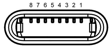
Type-C has 24 pins other than USB3’s 9 pins. Physically, USB Type-C receptacle looks smaller than its predecessor. It’s thin and packed.

| Pin | Name | Description |
|---|---|---|
| A1 | GND | Ground return |
| A2 | SSTXp1 | SuperSpeed differential pair #1, TX, positive |
| A3 | SSTXn1 | SuperSpeed differential pair #1, TX, negative |
| A4 | VBUS | Bus power |
| A5 | CC1 | Configuration channel |
| A6 | Dp1 | USB 2.0 differential pair, position 1, positive |
| A7 | Dn1 | USB 2.0 differential pair, position 1, negative |
| A8 | SBU1 | Sideband use (SBU) |
| A9 | VBUS | Bus power |
| A10 | SSRXn2 | SuperSpeed differential pair #4, RX, negative |
| A11 | SSRXp2 | SuperSpeed differential pair #4, RX, positive |
| A12 | GND | Ground return |
| Pin | Name | Description |
|---|---|---|
| B12 | GND | Ground return |
| B11 | SSRXp1 | SuperSpeed differential pair #2, RX, positive |
| B10 | SSRXn1 | SuperSpeed differential pair #2, RX, negative |
| B9 | VBUS | Bus power |
| B8 | SBU2 | Sideband use (SBU) |
| B7 | Dn2 | USB 2.0 differential pair, position 2, negative</sup> |
| B6 | Dp2 | USB 2.0 differential pair, position 2, positive</sup> |
| B5 | CC2 | Configuration channel |
| B4 | VBUS | Bus power |
| B3 | SSTXn2 | SuperSpeed differential pair #3, TX, negative |
| B2 | SSTXp2 | SuperSpeed differential pair #3, TX, positive |
| B1 | GND | Ground return |
Type-C has 4 power and 4 ground pins, 2 differential pairs for USB 2.0 data, 4 shielded differential pairs for USB 3.x data, and other pins. With USB Power Deliviery standard, a series of power profiles are supported. So a USB cable and power source can support 0.5W to 100W. Of course, it depends on the cable, host and devices for the power and data speed. USB 4 shall provide a maximum 40Gbit data link.
USB 4 introduces 5 alternate modes to support converters and other protocols. There are 3 types of USB Type-C cables. Firstly, full featured Type-C cable supports USB3.2 performance and other alternate connection such as DisplayPort, MHL, HDMI and Thunderbolt. Secondly, Thunderbolt 3 Type-C to Type-C (40Gbit/s) is another type of cable which can only be used as USB2 cable other than Thunderbolt 3. Lastly, adapter cables will be available. They will have their signs indicating their ability. The best option seems to be use full featured USB 4 Type-C cables and connectors. Otherwise, we have to respect what type of USB cables are. They might not work as expected even they look like the same.
Lightning
Apple built Lightning connector and used it in every Apple mobile devices since 2012. It’s a great connector for its use. Lightning connector is not even replaced by USB-C while Macbook Pro strives to push forward the industry standard practice.
| Pin 1 | GND | Ground | |
|---|---|---|---|
| Pin 2 | L0p | Lane 0 positive | |
| Pin 3 | L0n | Lane 0 negative | |
| Pin 4 | ID0 | Identification/control 0 | |
| Pin 5 | PWR | Power (charger or battery) | |
| Pin 6 | L1n | Lane 1 negative | |
| Pin 7 | L1p | Lane 1 positive | |
| Pin 8 | ID1 | Identification/control 1 | |
| Lane 0 and 1 may swap in IC of device connector (lanes don't swap if the accessory identification chip is connected to the ID0 pin) | |||
While the connector has certain layout, Lightning cables can be adapative because of Apple certified chip included in the cable. All pins seem to be able to switch between data and power. iPhone supports fast charging so the connector can support 18W charger at least. However, the speed is a secret. Sidecar feature which extends macOS screen to an iPad shows the eviendence of a fast transfering speed.
HDMI
HDMI is usually used to connect a display device which is surprisingly popular. It’s not replaced by thunderbolt/USB4 yet, allegedly because of its price advantage. Being a audio/video transmission interface, HDMI has its roots with its predecessor DVI. Starting from HDMI 2.1, its encoding becomes similiar to USB3 and supports 48Gbit/s data transfering speed.

| Pin 1 | TMDS Data2+ |
|---|---|
| Pin 2 | TMDS Data2 Shield |
| Pin 3 | TMDS Data2− |
| Pin 4 | TMDS Data1+ |
| Pin 5 | TMDS Data1 Shield |
| Pin 6 | TMDS Data1− |
| Pin 7 | TMDS Data0+ |
| Pin 8 | TMDS Data0 Shield |
| Pin 9 | TMDS Data0− |
| Pin 10 | TMDS Clock+ |
| Pin 11 | TMDS Clock Shield |
| Pin 12 | TMDS Clock− |
| Pin 13 | CEC |
| Pin 14 |
|
| Pin 15 | SCL (I²C serial clock for DDC) |
| Pin 16 | SDA (I²C serial data for DDC) |
| Pin 17 | Ground (for DDC, CEC, ARC, and HEC) |
| Pin 18 | +5 V (min. 0.055 A) |
| Pin 19 |
|
SATA
SATA (Serial AT Attachment) can be commonly found with storage devices. Various of hard drives and SSDs use SATA for power and data transfer. M.2 connector may also use SATA bus but those devices does not use SATA connectors.
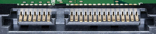
Its data connector has 7 pins and is much smaller than PATA connector.
| Pin # | Mating | Function | |
|---|---|---|---|
| 1 | 1st | Ground | |
| 2 | 2nd | A+ (transmit) | |
| 3 | 2nd | A− (transmit) | |
| 4 | 1st | Ground | |
| 5 | 2nd | B− (receive) | |
| 6 | 2nd | B+ (receive) | |
| 7 | 1st | Ground | |
| — | Coding notch | ||
Its power connector has a 15 pin connector with various of voltages.
| Pin # | Mating | Function | |
|---|---|---|---|
| — | Coding notch | ||
| 1 | 3rd | 3.3 V Power | |
| 2 | 3rd | ||
| 3 | 2nd | Enter/exit Power Disable (PWDIS) mode (3.3 V Power, Pre-charge prior to SATA 3.3) | |
| 4 | 1st | Ground | |
| 5 | 2nd | ||
| 6 | 2nd | ||
| 7 | 2nd | 5 V Power, Pre-charge | |
| 8 | 3rd | 5 V Power | |
| 9 | 3rd | ||
| 10 | 2nd | Ground | |
| 11 | 3rd | Staggered spinup/activity | |
| 12 | 1st | Ground | |
| 13 | 2nd | 12 V Power, Pre-charge | |
| 14 | 3rd | 12 V Power | |
| 15 | 3rd | ||
The latest standard supports 6Gbit/s transfering speed.
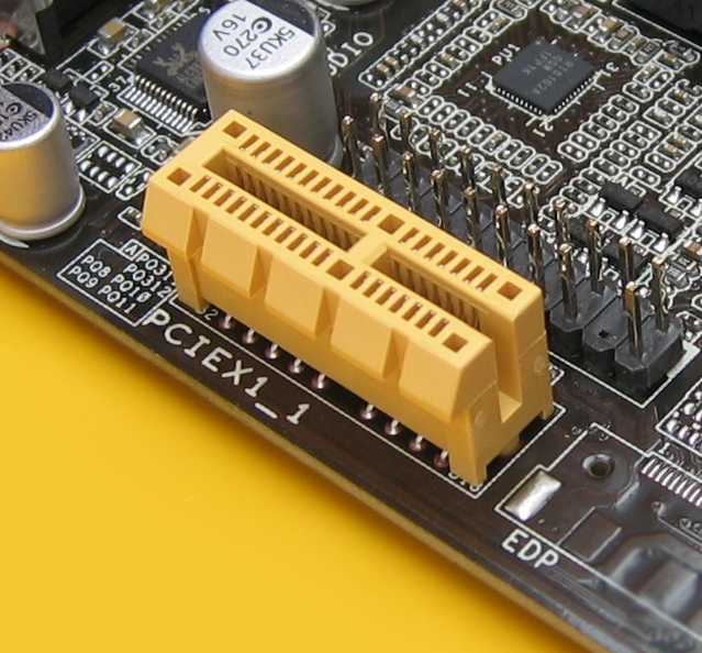
PCI Express
PCI-E has been the primary choices for devices that are inter-connected on the motherboard. PCI-E device communicates point-to-point with each other and use packets. PCI-E link varies from one to 32 lanes. Devices can be plugged into another PCI-E sockets. Link speed is negotiated to the maximum possible speed.
| Pin | Side B | Side A | Description | Pin | Side B | Side A | Description | |
|---|---|---|---|---|---|---|---|---|
| 1 | +12 V | PRSNT1# | Must connect to farthest PRSNT2# pin | 50 | HSOp(8) | Reserved | Lane 8 transmit data, + and − | |
| 2 | +12 V | +12 V | Main power pins | 51 | HSOn(8) | Ground | ||
| 3 | +12 V | +12 V | 52 | Ground | HSIp(8) | Lane 8 receive data, + and − | ||
| 4 | Ground | Ground | 53 | Ground | HSIn(8) | |||
| 5 | SMCLK | TCK | SMBus and JTAG port pins | 54 | HSOp(9) | Ground | Lane 9 transmit data, + and − | |
| 6 | SMDAT | TDI | 55 | HSOn(9) | Ground | |||
| 7 | Ground | TDO | 56 | Ground | HSIp(9) | Lane 9 receive data, + and − | ||
| 8 | +3.3 V | TMS | 57 | Ground | HSIn(9) | |||
| 9 | TRST# | +3.3 V | 58 | HSOp(10) | Ground | Lane 10 transmit data, + and − | ||
| 10 | +3.3 V aux | +3.3 V | Standby power | 59 | HSOn(10) | Ground | ||
| 11 | WAKE# | PERST# | Link reactivation; fundamental reset | 60 | Ground | HSIp(10) | Lane 10 receive data, + and − | |
| Key notch | 61 | Ground | HSIn(10) | |||||
| 12 | CLKREQ# | Ground | Clock Request Signal | 62 | HSOp(11) | Ground | Lane 11 transmit data, + and − | |
| 13 | Ground | REFCLK+ | Reference clock differential pair | 63 | HSOn(11) | Ground | ||
| 14 | HSOp(0) | REFCLK− | Lane 0 transmit data, + and − | 64 | Ground | HSIp(11) | Lane 11 receive data, + and − | |
| 15 | HSOn(0) | Ground | 65 | Ground | HSIn(11) | |||
| 16 | Ground | HSIp(0) | Lane 0 receive data, + and − | 66 | HSOp(12) | Ground | Lane 12 transmit data, + and − | |
| 17 | PRSNT2# | HSIn(0) | 67 | HSOn(12) | Ground | |||
| 18 | Ground | Ground | 68 | Ground | HSIp(12) | Lane 12 receive data, + and − | ||
| PCI Express x1 cards end at pin 18 | 69 | Ground | HSIn(12) | |||||
| 19 | HSOp(1) | Reserved | Lane 1 transmit data, + and − | 70 | HSOp(13) | Ground | Lane 13 transmit data, + and − | |
| 20 | HSOn(1) | Ground | 71 | HSOn(13) | Ground | |||
| 21 | Ground | HSIp(1) | Lane 1 receive data, + and − | 72 | Ground | HSIp(13) | Lane 13 receive data, + and − | |
| 22 | Ground | HSIn(1) | 73 | Ground | HSIn(13) | |||
| 23 | HSOp(2) | Ground | Lane 2 transmit data, + and − | 74 | HSOp(14) | Ground | Lane 14 transmit data, + and − | |
| 24 | HSOn(2) | Ground | 75 | HSOn(14) | Ground | |||
| 25 | Ground | HSIp(2) | Lane 2 receive data, + and − | 76 | Ground | HSIp(14) | Lane 14 receive data, + and − | |
| 26 | Ground | HSIn(2) | 77 | Ground | HSIn(14) | |||
| 27 | HSOp(3) | Ground | Lane 3 transmit data, + and − | 78 | HSOp(15) | Ground | Lane 15 transmit data, + and − | |
| 28 | HSOn(3) | Ground | 79 | HSOn(15) | Ground | |||
| 29 | Ground | HSIp(3) | Lane 3 receive data, + and − | 80 | Ground | HSIp(15) | Lane 15 receive data, + and − | |
| 30 | PWRBRK# | HSIn(3) | 81 | PRSNT2# | HSIn(15) | |||
| 31 | PRSNT2# | Ground | 82 | Reserved | Ground | |||
| 32 | Ground | Reserved | ||||||
| PCI Express x4 cards end at pin 32 | ||||||||
| 33 | HSOp(4) | Reserved | Lane 4 transmit data, + and − | |||||
| 34 | HSOn(4) | Ground | ||||||
| 35 | Ground | HSIp(4) | Lane 4 receive data, + and − | |||||
| 36 | Ground | HSIn(4) | ||||||
| 37 | HSOp(5) | Ground | Lane 5 transmit data, + and − | |||||
| 38 | HSOn(5) | Ground | ||||||
| 39 | Ground | HSIp(5) | Lane 5 receive data, + and − | |||||
| 40 | Ground | HSIn(5) | ||||||
| 41 | HSOp(6) | Ground | Lane 6 transmit data, + and − | |||||
| 42 | HSOn(6) | Ground | ||||||
| 43 | Ground | HSIp(6) | Lane 6 receive data, + and − | Legend | ||||
| 44 | Ground | HSIn(6) | Ground pin | Zero volt reference | ||||
| 45 | HSOp(7) | Ground | Lane 7 transmit data, + and − | Power pin | Supplies power to the PCIe card | |||
| 46 | HSOn(7) | Ground | Card-to-host pin | Signal from the card to the motherboard | ||||
| 47 | Ground | HSIp(7) | Lane 7 receive data, + and − | Host-to-card pin | Signal from the motherboard to the card | |||
| 48 | PRSNT2# | HSIn(7) | Open drain | May be pulled low or sensed by multiple cards | ||||
| 49 | Ground | Ground | Sense pin | Tied together on card | ||||
| PCI Express x8 cards end at pin 49 | Reserved | Not presently used, do not connect | ||||||
Summary
Connectors have different shapes optimized for different tasks. When devices or system evovles, connectors follows. A standard might try to extend its usage with designs but it does not fit every devices or future use cases. All these connectors provide essential functions such as power delivery, data transfering, some sorts of confugration pins. The way they were designed depends on its historical design and constraints.
Share on
X Facebook LinkedIn BlueskyComments are configured with provider: disqus, but are disabled in non-production environments.